The Electrochemical Society hosted Dr. Toby Bond’s webinar, “The Complex and Spatially Heterogeneous Nature of Degradation in Heavily Cycled Li-ion Cells,” on April 23, 2025. A live Question and Answer (Q&A) session followed. Dr. Bond’s written answers to some questions not addressed during the broadcast follow.
Note: Registration is required to view the webinar replay.
More information about Dr. Bond and the webinar abstract are here.
Q&A
Are there any techniques to break down overpotential increases and assign them to this cracking?
It’s difficult to attribute increases in impedance directly to microcracking (and the associated cathode surface reconstruction). Using a technique like in situ CT, you can at least identify whether microcracking is taking place and assume it is contributing to increased impedance. If you disassemble the cell, you can then take separate impedance measurements for the anode and cathode to figure out which electrode is contributing more to the impedance increase. Even at that point, it would be difficult to separate out the fraction of impedance that is due to microcracking and surface reconstruction from all other potential sources of impedance.
Is it possible to identify and account for the change in thickness of the electrode caused by CEI/ SEI layer and lithium plating?
SEI/CEI layers are so thin (typically low tens of nm) that they are not observable via CT, and Li metal is so light that it is very challenging to image with x-rays in a commercial cell. So, the short answer is that we can’t separate out any thickness growth due to these factors using in situ measurements. We tend to focus more on the cathode when doing x-ray CT of commercial cells because it has a much higher inherent contrast than graphite, as it is composed of heavier elements with higher x-ray attenuation. Studying low-contrast features like Li plating and anode microstructure is typically done using purpose-built in situ cells that allow us to use lower-energy x-rays and obtain better image quality.
How can we avoid microcracking?
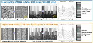
If you have a battery with a conventional polycrystalline NMC/NCA cathode, you can limit microcracking by reducing the voltage window over which it is charged, which in turn reduces the degree of anisotropic volume expansion/contraction. For example, if you’re driving an EV to work every day, you would be better off charging it every night as opposed to deep-cycling the battery to 0 percent, then fully recharging it. A larger number of shallow cycles is much better at preventing microcracking than a smaller number of deep cycles, so being able to charge at home or work is really helpful for this. Many recent EV batteries with nickel-rich cathodes also have a critical point around the 80 percent state-of-charge mark where there is a sharp increase in the degree of cathode volume contraction. For batteries like this, the best practice is to charge the battery to something like 75 percent for daily driving, and only charge to 100 percent for longer trips when you need the extra range (you will often see something along these lines stated in EV owners’ manuals).
Which single crystal can be used as a cathode and what are the disadvantages of using SC cathodes?
Any NMC or NCA material can be made into a single-crystal cathode, and there are many such materials available on the market. Historically, the main disadvantage of single-crystal materials has been that they were more complex to synthesize and have been produced at much smaller scale, both of which lead to higher costs compared to polycrystalline cathodes. Most of that premium has now been erased however, as synthesis protocols have been optimized and single-crystal materials are now produced in very high volumes by large companies like CATL and LG Chem.
One other drawback of single-crystal materials is that Li diffuses more slowly through the bulk of the crystallite compared to the grain boundary, so the lithiation kinetics are somewhat slower compared to polycrystalline cathodes. To mitigate this, single-crystal particles are generally made smaller (typically 1-2 μm in diameter) than secondary particles of polycrystalline electrodes (5-10 μm).
Regarding microcracking, how is that with LFP? Any idea? Also, is there research going on to identify the best transition metal that can support the cathode integrity while Li is moved?
Microcracking can occur in LFP, but it is generally much less of a concern. Although volume expansion/contraction still occurs in LFP, it is not nearly as anisotropic as with NMC/NCA. LFP particles are also much smaller, typically on the order of hundreds of nm, so they don’t build up these complex patterns of stress and strain that you find within secondary particles of NMC/NCA. However, microcracking can occur in specific LFP materials with larger particles that are designed to have low-surface area. For the most part however, LFP particles are kept very small to maintain rate capability.
There is indeed published research on doping NMC/NCA with stabilizing elements. Some of the more popular ones include tungsten, tantalum, fluorine, and boron. These elements stabilize the lattice to some degree and can suppress the effects of microcracking. There are also many other materials-based approaches to preventing microcracking, like particle coating and core-shell structures.
Learn more about upcoming ECS Webinars and review our previous webinar recordings.
Thanks to the webinar sponsors who make these complimentary programs possible!
Interested in presenting an ECS Webinar?
Email your presentation title and abstract to education@electrochem.org for consideration.


