

Prof. Nagappan Ramaswamy
The Electrochemical Society hosted “Fuel Cell Catalyst Requirements for Heavy-Duty Vehicle Applications,” a live webinar by Nagappan Ramaswamy (Indian Institute of Technology Bombay), on February 18, 2026. A live Question and Answer session followed. Answers to questions not addressed during the broadcast are provided below.
Replay webinar
(Click to enlarge)
Q&A
How does decreasing ionomer fraction affect the BOL performance? Is there a trade-off between initial performance and durability?
In general, a decrease in the ionomer fraction yields lower BOL performance since the proton conductivity decreases and the continuity of ionomer distribution is also interrupted. The catalyst layer is usually well optimized for maximum performance. In a well-optimized catalyst layer, there is typically no trade-off between performance and durability.
What would be the yield if you completely removed Pt and use Co or its alloy with a lower cost catalysis?
Non-Pt catalysts are not practical for PEM fuel cell applications, as they (i) are not durable under dynamic load-cycling conditions; and (ii) do not meet heat rejection requirements for automotive applications.
Given that some major players are struggling to commercialize PEM vehicles or even sustain programs, what do you think is the viability of the technology, irrespective of the policy mandates?
It’s likely to remain a niche technology for the foreseeable future. We electrochemists only talk about the high stack efficiency of ~60%, but if you look at the entire lifecycle of a fuel cell, the total efficiency of going from water to electricity is ~25% (this involves two energy conversion processes). One use case could be in the so-called hard-to-decarbonize sectors such as class-8 long-distance trucks. Here batteries may not be suitable as their weight takes up some of the truck payload. Another use case is for countries, from an energy security perspective, which want to be completely free of fossil fuels.
What could be the role of catalyst layer preparation method on efficiency and durability?
It’s an extremely important step. Typically, in academics, the focus is only on catalyst synthesis. The catalyst layer prep is often overlooked. The fabrication of catalyst inks involves a lot of rheology. The microstructure of the catalyst layer is formed in the catalyst ink stage. The role of catalyst layer on durability is very significant. Poorly optimized catalyst inks and layers usually lead to very poor durability.
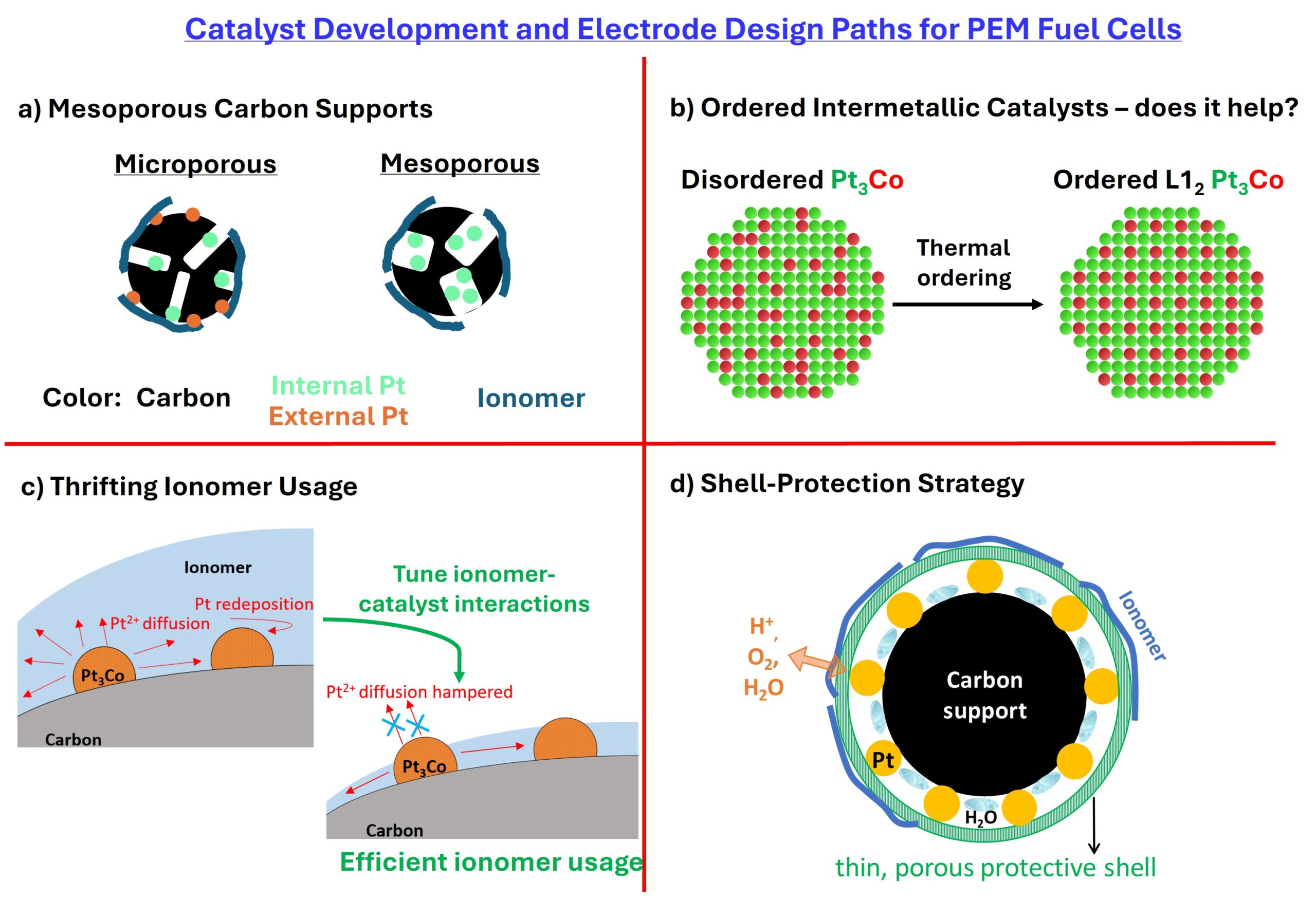
The size of the conventional carbon supports is 40-50 nm and has chained structure. When we use large size and separated porous carbon, large voids are formed in the cathode catalyst layer. Do you think that the large size voids contribute to high cell voltage in high current density region compared with the conventional small and chained-structured porous carbon support?
I don’t think so. Based on our work, the data point to the significance of intrinsic mesopores within the particle structure. The voltage loss at high-current densities in a typical 40-50 nm sized carbon-based layer arises from the pressure-independent O2 transport resistances (local-O2 transport resistance) due to the constricted microporous openings (2-3 nm) in these carbon particles that limit O2 transport. The bulk O2 transport is not a limiting case. As we transition to the mesoporous carbons, the openings of the carbon particles are slightly enlarged (4 to 7 nm) that let O2 pass through with less resistance. The bulk-O2 transport resistance from limiting current density measurements from both these carbons is roughly the same.
Is there any best practice procedure for transient (start-up/shut-down, load change) that could minimize the cathode degradation?
Typically, automotive companies prevent the fuel cells from reaching high potentials that cause cathode degradation. Most of the degradation occurs when the fuel cell cathode reaches potentials of 0.9 V or higher.
How do the graphitic properties of the carbon host affect the catalytic performance? If it does improve the catalytic performance, how to achieve it?
The carbon support graphitization levels are really a trade-off between carbon corrosion (in the load cycling regime of 0.60 to 0.95 V) and the catalyst nanoparticle durability. Graphitic carbons lead to improved corrosion stability but lead to poor Pt durability as they accelerate Pt migration-coalescence.
Current state of the art KetjenBlack-EC300J type carbons feature ~800 m2/g. I think there is some room for graphitization down to 500 m2/g. In heavy-duty applications, the durability requirement is ~30,000 hours of operation (compared to ~8,000 for light duty vehicles). During the load-cycling operation (0.60 to 0.95 V), there could be some changes in the hydrophilicity of the carbon support due to repeated oxidation. If some graphitization could be achieved without compromising Pt durability, then that could be useful.
How does alloying other Pt-alloys like Ta, Zr affect the electrode electronic conductivity?
Usually, small quantities of the alloying elements (~3% by weight of carbon) do not affect electronic conductivity to any significant extent. There is enough carbon for electronic conductivity.
Do you consider Pt/Au alloys as a potential catalyst as the dissolution can be suppressed?
This could be an option if Au (either on the surface or subsurface) could stabilize under-coordinated Pt sites that are more susceptible to corrosion.
How do you think the Pt-skin structure can prevent the Pt dissolution in Pt alloy?
From a durability perspective, it all depends on how resistant the Pt-skin layer is toward the formation and reduction of the subsurface, place-exchanged oxide layer (Pt-O). The subsurface alloying element could prevent or delay the formation of place-exchanged oxide (so that the Pt-skin catalyst needs higher potentials in the anode cycle) or delay the reduction of place-exchanged oxide (so that Pt-skin catalyst needs a very low potential in the subsequent cathodic cycle). This is just my understanding based on my reading of the subject. I don’t have any data to confirm or deny it.
Can you tell us how to protect Pt dissolution?
A few suggestions: Use porous carbons; evaluate alternative Pt-alloys; clip the upper potential and lower potentials so that the fuel cell operates within a narrow window; experiment with shell-protection strategies (particularly carbon or metal oxide nanocluster shells); thrift ionomer volume fraction.
You mentioned that some metal oxides combined with Pt-based catalysts may dissolve. Could you clarify which oxides are most vulnerable and whether dissolution is mainly driven by potential, acidity, or reactive species such as H₂O₂ (e.g., in the case of TaOx)?
This is an open area of research. I don’t know particularly in the case of TaOx. Some studies by Strasser et al (reference 158 in the article) point to the use of Ti- and Ru-based oxides which dissolve during load cycling (~0.6 to 0.95 V) and then redeposit on Pt to block the active sites. Most likely, the potential cycling is the dominant parameter followed by acidity.
Would alloys between Pt and early transition metals like Nb, Zr, Ta, and W have problems with oxidation of the early transition metals?
Certainly yes. The stabilization of these alloying metals within the Pt nanoparticle could be a challenge. Some new synthesis strategies are needed here. An understanding of the thermal phase diagrams to identify stable alloying structures could be a good starting point.
Learn more about upcoming ECS Webinars and review previous webinar recordings.
Interested in presenting in the ECS Webinar Series? Email your presentation title and abstract to education@electrochem.org for consideration.